A DIY Touch Probe
I recently invested in the Tormach Tooling System (TTS) for my CNCed SX3. So far I’m really impressed with the set. Tool changes couldn’t get much easier. One of the best things about the system is that the holders give each tool a very repeatable height. That means that I can account for height offsets in my program and have one less thing to worry about when it is time for a tool change. But I still didn’t have an easy way to locate the spindle in relation to my workpiece. For me, this was a manual process of edge finding repeated for each axis. There had to be a better way…
After doing a bit of research it seemed like a touch probe would solve my problem and, lucky me, there are a few people who have had success building their own. See here and here and here and here.
Theory
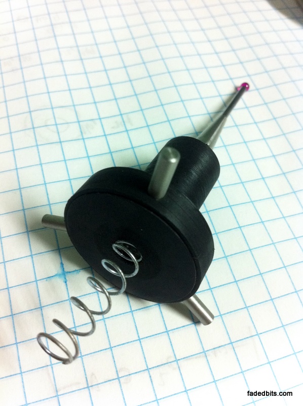
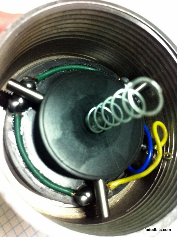
The operating principle of this type of probe is pretty simple. They consist of three conductive rods, mounted perpendicular to the probe tip, each resting in a pair of conductive balls. The balls are wired together such that a signal will pass through the assembly when the rods are each in contact with their respective balls. If any of the rods move and contact is lost with one or more balls then the circuit is broken and a detectable change in the signal occurs.
Make sense? Let’s build one!
Construction
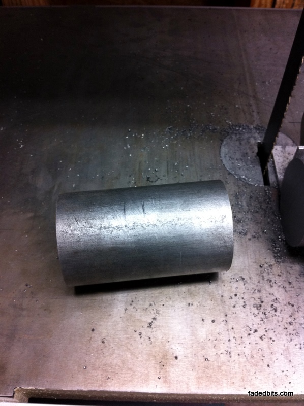
Mine started off with a few inches of 12L14 2.25″ round rod.
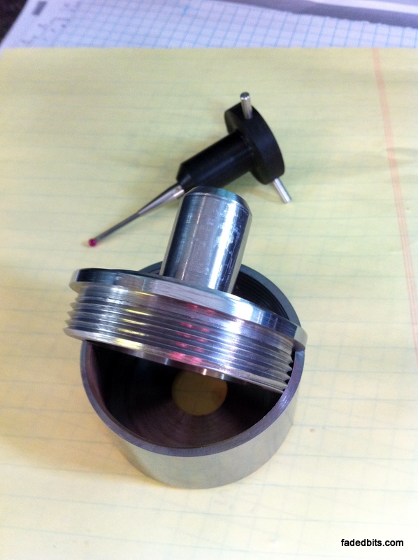
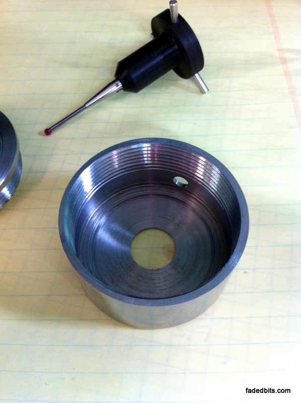
This was turned in the lathe to produce two pieces. The first was a TTS style holder and the second a housing that will hold the touch probe assembly.
The probe was turned from black delrin and has three 0.125″ steel dowel pins pressed into the larger diameter. It is a good idea to use a rigid material for this part and you could probably do better then delrin. If you look for a better material remember that it must be non-conductive, the rods must be electrically isolated from each other or the probe will not work. At the end of the smaller diameter is a Renishaw styli. You can purchase the styli here for a reasonable price. A spring in the top of the probe puts pressure on the assembly and helps make sure that the steel dowel pins stay in contact with the bottom of the assembly.
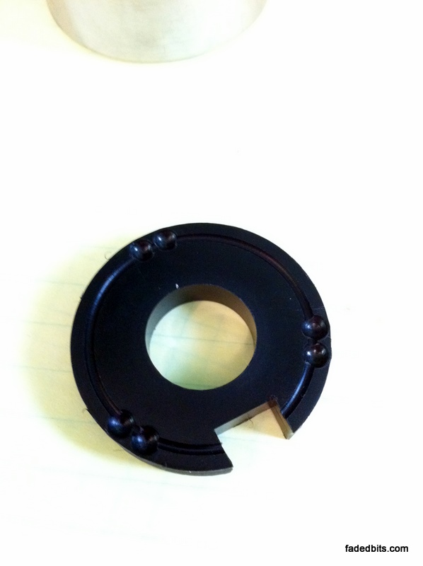
The bottom of the assembly is again turned from black delrin and has six pockets machined in it to receive steel balls. There is also a trough milled around the perimeter providing a place to secure the wire that will be used to construct the circuit. A notch is taken from the edge of the plate to allow clearance for the 1/8″ stereo plug mounted in the touch probe’s housing.
After initial assembly I measured the runout of the probe tip and found it unacceptable. The ball plate originally was pressed into a pocket in the bottom of the housing. I enlarged the pocket nearly to the inside wall of the housing and then added three set screws around the perimeter of the housing allowing for some adjustment in the position of the ball plate. With these improvements I am able to reduce the runout to about 0.00025″ which should be more than enough for anything that I’m likely to do.
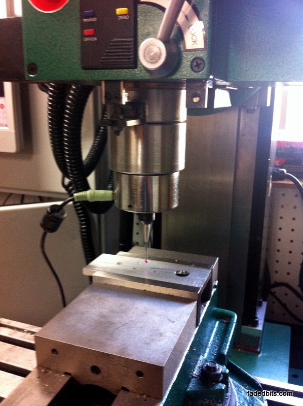
Here is the probe mounted in the mill, a standard audio cable carries the signal to the CNC control box.
Setting up EMC
This part is easy! You can use any any input-mode parallel port pin (10, 11, 12, 13, 15). I choose pin 13. One wire on the probe is supplied with +5V and the other is connected to pin 13 on the the parallel port (via a CNC4PC BOB). Then I added the following line to my hal file:
net probe parport.0.pin-13-in-not => motion.probe-input
That’s it! EMC will will now look to pin 13 for touch probe signal information.
Using the probe
Chris Radek has published some g-code routines on his site that got me up and running quick. I only had to make a couple of changes to account for the difference in probe ball diameter (his is 6mm, mine is 3mm).
Here is a video of the touch probe locating the top surface of a workpiece (a hunk of scrap to test with in this case). After locating the surface the probe tip moves to 0.2″ above the surface.
Here is a video of the touch probe locating the center of a circle. The probes uses a couple of rapid passes to roughly locate the center of the hole followed by a very slow approach to each located edge for a precise location. At the end of the program the probe tip is located in the center of the hole. On the screen (not shown) EMC2 displays the diameter for both X and Y axis.
That’s it! So far I’m really happy with the performance of the probe. Now I’m off to add probing steps to all my programs!
6 Responses to 'A DIY Touch Probe'
Leave a Reply
You must be logged in to post a comment.

[…] [Dennis] recently invested some money in the Tormach Tooling System for his CNC’d Sieg SX3 mill in order to make his tool changes easier. While the kit allows him to easily account for height offsets while changing tools, he has no quick, reliable means of locating the spindle in relation to his workpiece. Tired of manually finding the edges of his workpiece for each axis, he built himself a DIY touch probe to automate the process. […]
DIY CNC touch probe - Hack a Day
9 Jun 11 at 8:07 am
I’d be interested in hearing your experiences on how repeatable this probe appears to be as it ages and with temperature changes… How did you get the bearings to stay in place, and how did you get the wires to make reliable contact with the balls?
Thanks!
– Steve
scicior
9 Jun 11 at 10:13 am
Have you considered selling these? Some of us aren’t really fortunate enough to have access to lathes and stronger CNC mills required to do metal work but I would love to get one of these to use with my upcoming Probotix Commit upgrade.
Tumbleweed
tumbleweedlabs
9 Jun 11 at 1:19 pm
Do you have drawins or CAD files you would be willing to share? I like some of the design details you made with the probe holder and ball/wire connections.
Also, thanks for sharing your work!
EBo —
ebo
20 Oct 12 at 1:52 pm
I don’t have any CAD files for this one, sorry.
dennis
22 Oct 12 at 8:58 am
[…] […]
The new probe and finding the center of a hole
5 Jun 13 at 10:38 pm