Updated Flying Optics for the Laser Cutter
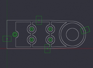
The worst part about using the laser cutter is aligning the optics. It only takes the smallest misalignment to cause big problems in the quality of the output and after trying multiple times to realign the laser with only mediocre results I decided that something a little more drastic was in order. The culprit seemed to be the carriage that carries the flying optics. It was made before the mill was converted to CNC and several of it’s measurements were off. Since the mill has been upgraded I was pretty confident that it could produce a much more accurate part. The first thing to do was draw up the part in CAD/CAM. For this I tried CamBam. They have a free trial good for 40 sessions after which it will still work for small projects. I’m new to the CAD/CAM world and have heard horror stories about the learning curve on some of the software packages available. CamBam was quick and easy. In a few minutes I was drawing up my part and not long after that I had a gcode file generated and ready for the mill. The design went through a couple of iterations before I settled on one that I liked. The final version looked like this:
I did a sanity check on the gcode by starting with and “air run”. Once everything looked OK it was time to start cutting some metal! Here is a (horribly poorly shot) video of the spot drill operation. At the end of the video you should be able to hear the Z axis jogging up to the tool change position and if you could see the EMC screen you would notice it asking for the next tool.
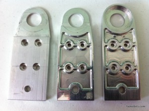
Here are the first three versions of the carriage side-by-side for comparison. On the left is the first part that was done on the manual mill. Next is the first CNC version with no material left surrounding the optics mount. In the next version I left a ring around the optics mount. This greatly increased the strength and helped locate the optics on the carriage. The final version isn’t pictured here but the only difference was a deeper cut in the three pockets around the mounting holes. The only reason for the pockets is to help reduce weight and lower the inertia on the laser cutter’s X axis. The final version of the carriage ended up weighing less than the original while at the same time being stronger and WAY more accurate.
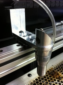
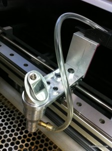
Here are a few pictures of the final version of the carriage installed on the laser cutter:
One Response to 'Updated Flying Optics for the Laser Cutter'
Leave a Reply
You must be logged in to post a comment.


[…] Updated Flying Optics for the Laser Cutter » fadedbits.comLVD INTRODUCES AUTOMATION-READY FLYING OPTICS LASER CUTTING SYSTEM FOR FAST, EFFICIENT SHEET METAL PROCESSING. Gullegem … […]
Flying optics | Healthhopeandh
13 Feb 12 at 7:54 am