Archive for the ‘Laser Cutter/Engraver’ Category
Updated Flying Optics for the Laser Cutter
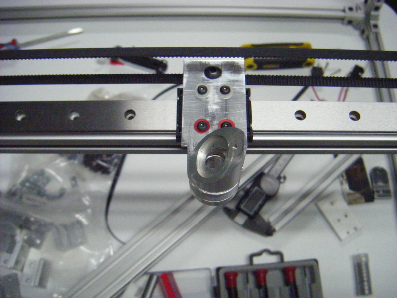
The worst part about using the laser cutter is aligning the optics. It only takes the smallest misalignment to cause big problems in the quality of the output and after trying multiple times to realign the laser with only mediocre results I decided that something a little more drastic was in order. The culprit seemed to be the carriage that carries the flying optics. It was made before the mill was converted to CNC and several of it’s measurements were off. Since the mill has been upgraded I was pretty confident that it could produce a much more accurate part. The first thing to do was draw up the part in CAD/CAM. For this I tried CamBam. They have a free trial good for 40 sessions after which it will still work for small projects. I’m new to the CAD/CAM world and have heard horror stories about the learning curve on some of the software packages available. CamBam was quick and easy. In a few minutes I was drawing up my part and not long after that I had a gcode file generated and ready for the mill. The design went through a couple of iterations before I settled on one that I liked. The final version looked like this: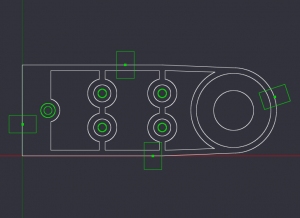
I did a sanity check on the gcode by starting with and “air run”. Once everything looked OK it was time to start cutting some metal! Here is a (horribly poorly shot) video of the spot drill operation. At the end of the video you should be able to hear the Z axis jogging up to the tool change position and if you could see the EMC screen you would notice it asking for the next tool.
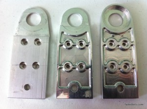
Here are the first three versions of the carriage side-by-side for comparison. On the left is the first part that was done on the manual mill. Next is the first CNC version with no material left surrounding the optics mount. In the next version I left a ring around the optics mount. This greatly increased the strength and helped locate the optics on the carriage. The final version isn’t pictured here but the only difference was a deeper cut in the three pockets around the mounting holes. The only reason for the pockets is to help reduce weight and lower the inertia on the laser cutter’s X axis. The final version of the carriage ended up weighing less than the original while at the same time being stronger and WAY more accurate.
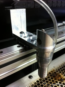
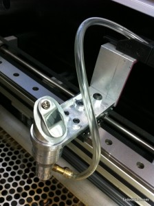
Here are a few pictures of the final version of the carriage installed on the laser cutter:
The Laser Cutter/Engraver (Part 2)
This is Part 2 of my Laser Cutter/Engraver build, you might want to check out Part 1 if you haven’t seen it.
Time for a little paint!
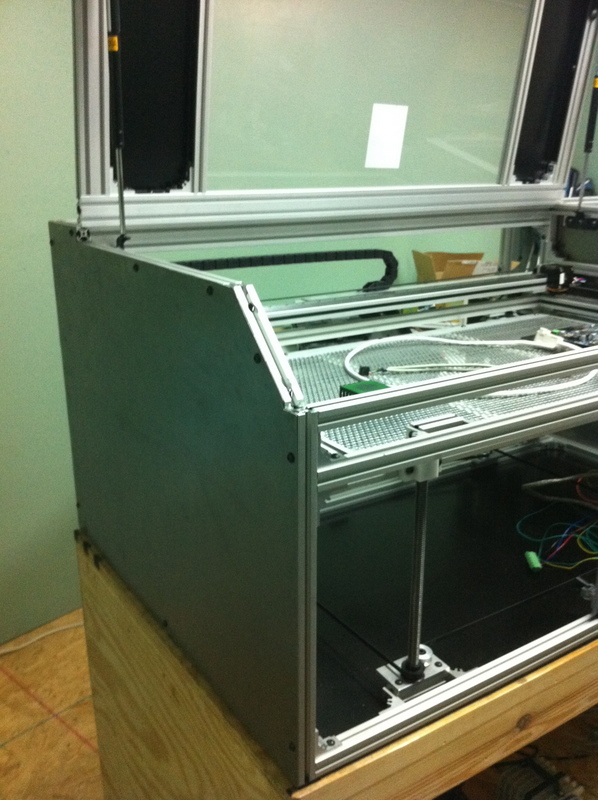
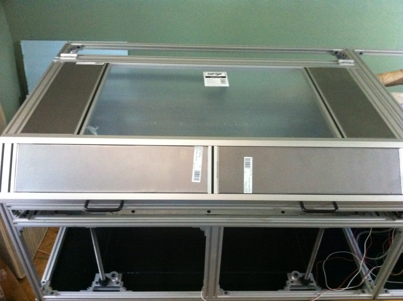
Larger sheets of steel will cover the ends of the machine.
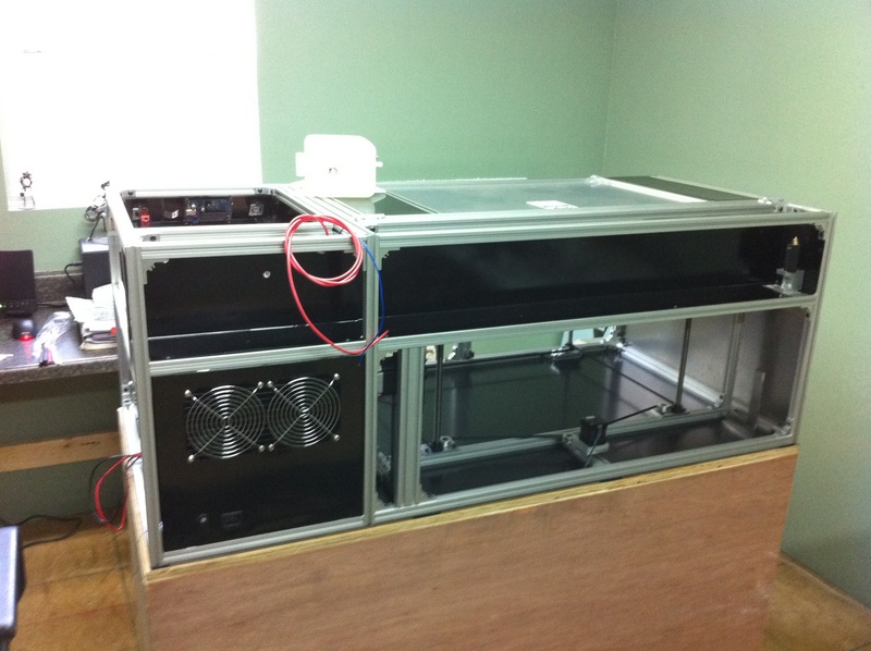
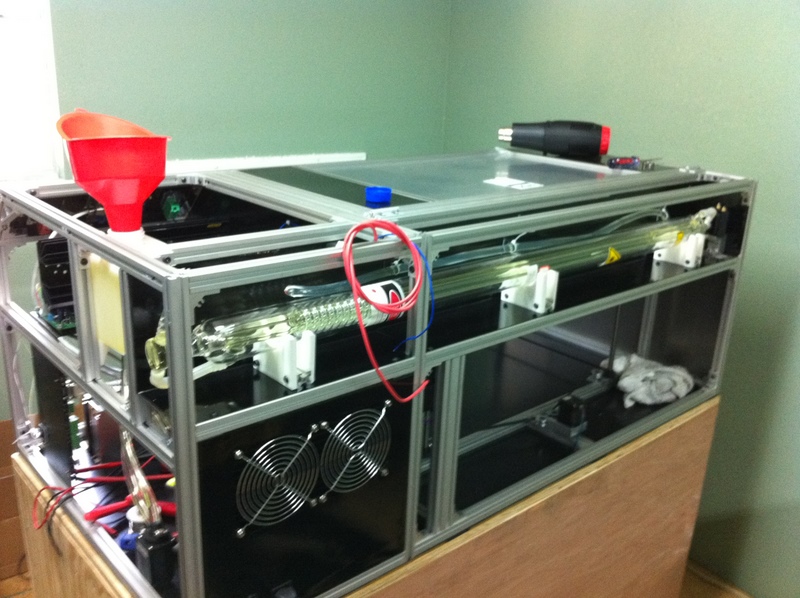
An enclosed area in the back of the machine will house the laser tube. Here you can see the laser tube’s home as well as the exhaust vent for the water cooling system (laser tubes get hot).
The first test fitting of the laser. The tube is actually longer than what the spec sheet claims, it just barely fits lengthwise in the enclosure.
Here’s a quick clip of some glass being etched. I was still playing around with calibrating the laser power level and the speed. This is REALLY SLOW.
And here’s the finished laser cutting out a design from thingiverse.com. The material is 5mm plywood that I had left over from another project.
The Laser Cutter/Engraver (Part 1)
I don’t remember now when it was that I first discovered laser cutters, but I do know that since that time I have wanted one. But a decent machine costs big $$$ and it was always well out of reach. (You can get inexpensive machines from overseas if you can accept the compromises in quality and features.) Then I stumbled across www.buildlog.net… with so many awesome examples of home built machines I couldn’t resist the temptation to give it a shot myself.
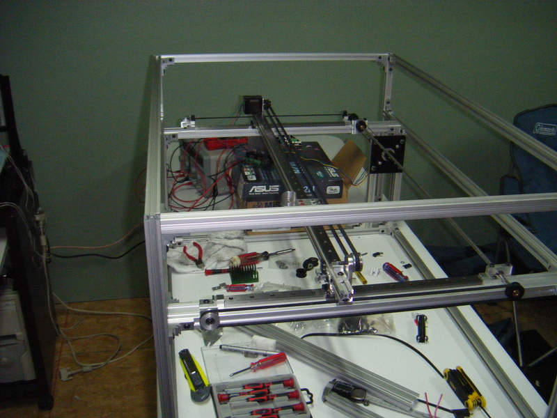
Here’s an early version of the frame. Hardly any of this design made it to the final build, but it worked well to test the motor controllers and belt drives.
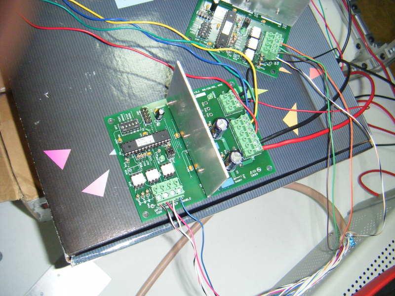
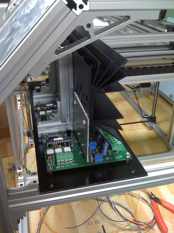
I decided to use AVRSMTD stepper motor drivers because the firmware is open source so I could make changes if needed. I only had to make very small changes to turn on the desired microstepping modes. The drivers have been working perfectly since. Here’s a pic.
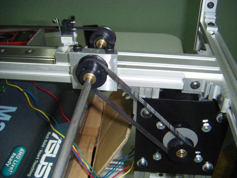
This is the belt drive for the Y axis.
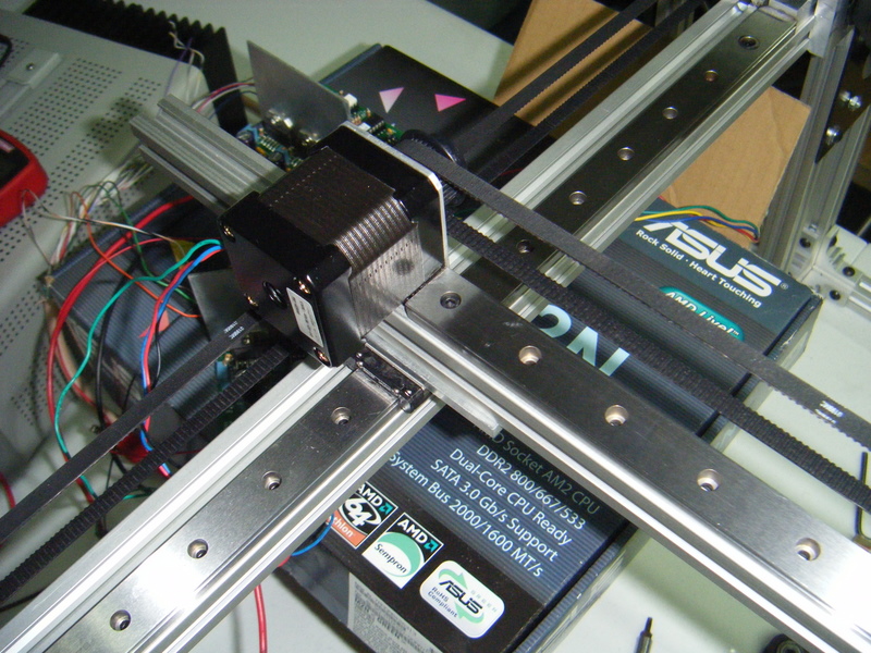
The X axis uses a nema 17 motor.
Here’s an early version of the flying optics.
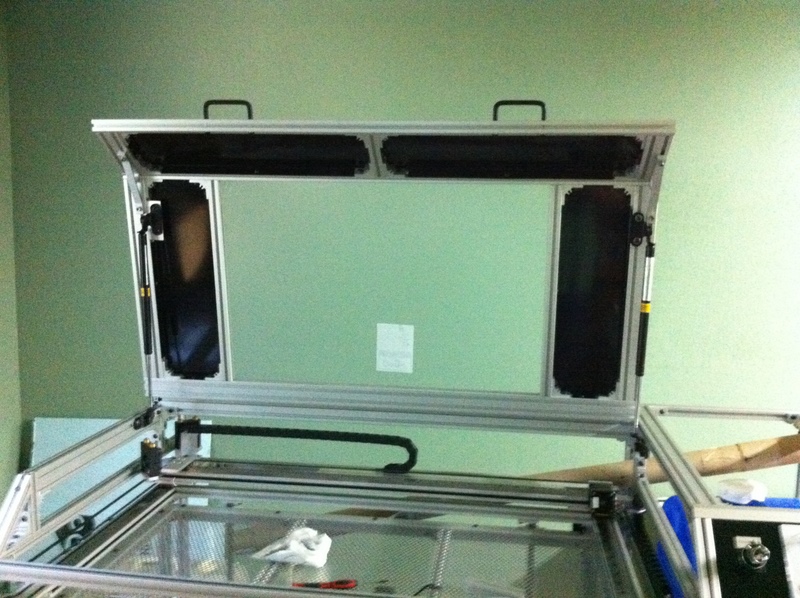
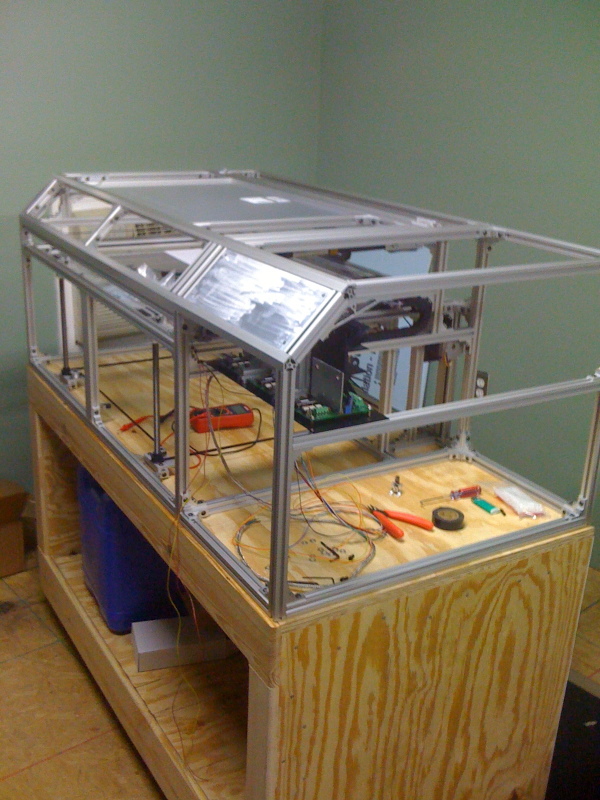
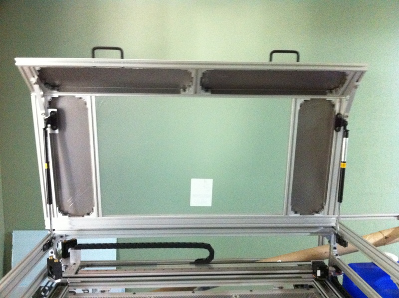
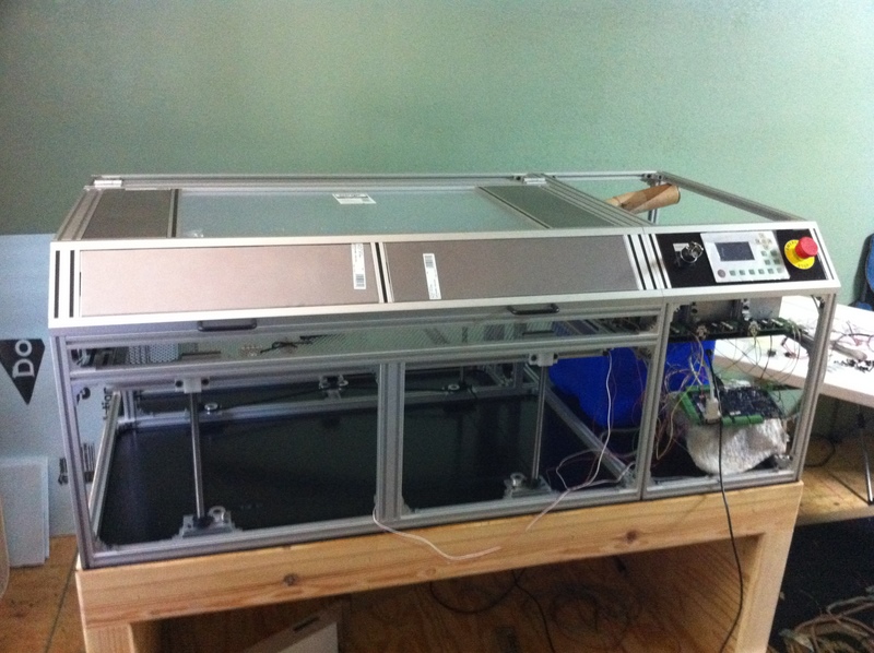
This is the final version of the frame starting to get some skins and a new rolling cart for the machine to live on.
The motor drivers get a new home (and a MUCH larger heatsink!)
The laser cutter can function in two modes. It can “print” a raster image much like an ink jet printer by scanning the X axis quickly back and forth and slowly advancing the Y axis. When in this mode the laser will pulse quickly, only firing on the black portion of the image. Alternatively, it can follow the curves of a vector image. This mode is used mostly for cutting material.
Here is a video I took while dialing in the speed of the X axis in raster mode.
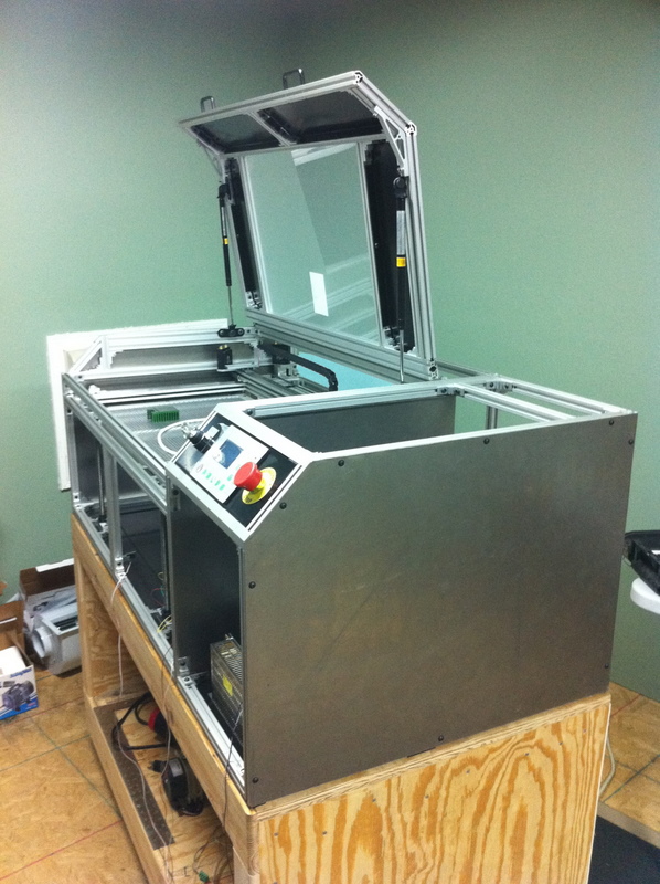
The skins are made out of light gauge steel panels bent at the edges and attached to the frame with screws.
Here you can see the mounted control panel. The system is driven by a DSP main board from LightObject.
The rest of the build can be seen in Part 2.
